|


| |
Ekco Continued,
Model A33 "Radiotime" Continued
Brief Description
Of The Operation Of The Timed Feature. 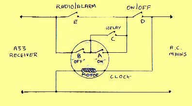 The clock motor is permanently connected to the mains supply, and has two
switches associated, switch "A" being the "ON" time and
"B" being the "OFF" time. The "ON" and
"OFF" times may be changed by controls protruding from the rear of the
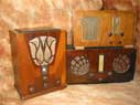
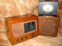
receiver (see picture previous page), and the actual times set are viewable thorough small windows to the
left and right of the clock hands (see picture below). At the predetermined time the "ON"
time is reached and closes switch "A" thereby switching on the
receiver. (Switch "B" is already closed). As the H.T. builds a relay
operates and closes contacts "C", short-circuiting switch
"A".
The clock motor is permanently connected to the mains supply, and has two
switches associated, switch "A" being the "ON" time and
"B" being the "OFF" time. The "ON" and
"OFF" times may be changed by controls protruding from the rear of the
receiver (see picture previous page), and the actual times set are viewable thorough small windows to the
left and right of the clock hands (see picture below). At the predetermined time the "ON"
time is reached and closes switch "A" thereby switching on the
receiver. (Switch "B" is already closed). As the H.T. builds a relay
operates and closes contacts "C", short-circuiting switch
"A". 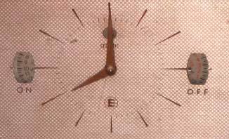 The relay is required because switch contacts "A" open
again after about 30 minutes and without the relay would have switched the
receiver off again. When the programmed time to switch the receiver off again is
reached switch "B" is opened. This switch also has a 30 minute delay
before it reverts, but as the "ON" switch "A" is now open
and the relay is no longer energised, current cannot flow through contact
"C", and the receiver remains turned off. Also shown on the diagram
are switches "D" and "E". "D" is the manual on/off
switch at the front of the receiver which overrides all clock timed functions,
and switch "E" is the "Radio/Alarm" switch. The relay is required because switch contacts "A" open
again after about 30 minutes and without the relay would have switched the
receiver off again. When the programmed time to switch the receiver off again is
reached switch "B" is opened. This switch also has a 30 minute delay
before it reverts, but as the "ON" switch "A" is now open
and the relay is no longer energised, current cannot flow through contact
"C", and the receiver remains turned off. Also shown on the diagram
are switches "D" and "E". "D" is the manual on/off
switch at the front of the receiver which overrides all clock timed functions,
and switch "E" is the "Radio/Alarm" switch.
Continue to the Ekco
U159
© COPYRIGHT RETAINED ON ALL TEXT AND PICTURES ON THIS SITE.
|