
|
|
|
|
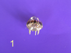
EF80 Pentode Valve Individual Component Parts
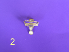
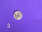
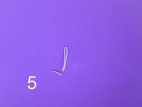
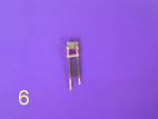
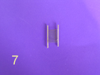
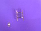
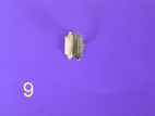
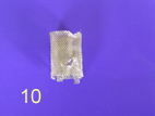
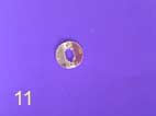
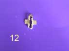
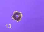
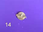
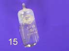
A valve is an extremely complex device, and there may be more components within that glass envelope than you might at first realise. To demonstrate this I have dismantled an EF80 valve to its main individual components. They can be seen above, but 15 is not the total number of parts. For instance, each valve pin is made of three individual pieces of metal. I chose an EF80 as it is one of the most commonly seen valves today, so every collector is likely to have a few. Also because I have several dozen so I could afford to cannibalise this one for the website! Health warning time - valves contain small sharp metal elements, some of which may be poisonous, held within a vacuum. Do not attempt this yourself unless you have taken appropriate safety precautions. A complete EF80 is at this page. The following is a brief explanation of each of the elements seen above. Generally speaking I am working upwards and/or outwards through the valve. 1 Glass base with pins incorporated. Each pin is constructed such that the metal passing "through" the glass is designed to expand at the same heat coefficient as the glass itself so that cracking or loss of vacuum cannot occur one hot. 2 Metal piece of base form metalwork. 3 Mica positioning and centring piece at base of valve. 4 Cathode, electrons emitted from here. 5 Heater. 6.3v passes through this wire to cause heating of the cathode. 6 Control grid, metal section at top is to aid heat dissipation. 7 Screen grid, fine wire wound between struts can barely be seen. 8 Suppressor grid, wire between posts increased gauge so just visible. 9 Anode, encompasses the valve grids to attract electrons from cathode. 10 Gauze electrostatic screen mesh. 11 Mica positioning piece at top of valve. 12 Metal forming and positioning piece at top of valve. 13 Mica centring piece at top of valve. 14 Getter plate, getter situated here prior to "firing". 15 Glass envelope with valve type and batch number, notice white dust at top which always indicates vacuum failure. (n.b. Since preparing the images etc for this page another site, the excellent r-type.org, has also uploaded a page detailing the components of an EF80 using a promotional prop from Mullard. I'm not generally in favour of duplication on the internet but it took a fair while to prepare these images so i'll let it remain here too! Also, becoming a member of the BVWS will entitle you to a DVD of a promotional film made by Mullard in the 1950s showing the assembly of an EF80) Continue to Frequency
Converter Gallery Page Return to main Valve Subsection Menu © COPYRIGHT RETAINED ON ALL TEXT AND PICTURES ON THIS SITE 2005 AND BEYOND. |